DPDT switch serial cable
(for devices that don't require hardware flow control or anything fancier than a single pair each for transmit/receive)
THESE INSTRUCTIONS ARE ALL AT YOUR OWN RISK. Serial connections are electrical in nature, and often used to administer very expensive equipment. Quite frankly, you are on your own if you chose to make one of these, I'm writing this up largely for my own information (if I ever need to make another one ;). If you make a bad cable that ends up causing damage to something it is your own responsibility.
This is a reconstruction of something I put together years ago. I may have omitted some steps, etc. Some imagination may be required.
Materials:
- (2) RJ45 to DB9 Adapters. The ones I have come with Cisco gear for use with their blue rollover cables. They are labeled "Terminal" on one side, and "74-0495-01" on the other.
- (2) DB9 gender changers. The ones I have are labeled "Gender Changer U.S. PAT: 5190481
- (1) Ethernet cable, terminated straight-through with RJ45 plugs on each end.
- (1) Double-pole double-throw (DPDT) switch, small enough to fit within the housing of the RJ45/DB9 adapter
Tools:
- Soldering iron, solder
- DB9 extraction tool
- Wire cutters
Steps:
Disassemble the RJ45/DB9 adapter. The DB9 end should just pop off. There entire assembly can then be slid out (there is a catch on the other side that needs to be depressed with *just* the right tool, its tricky) and looks something like this:
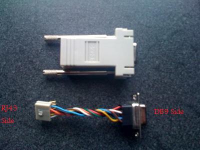 On the RJ45 side, we're only interested in four wires. In my case, they were the Green, Red, Yellow and Black. Leave those alone, the others can be snipped.
On the DB9 side, use the extraction tool to remove all but the red and green wires. Note where the yellow and black used to be, that is where we'll be inserting new wires later. Save the snipped wires, we will need them to make additional connections.
Take two of the wires (in my case I used the blue and orange) and re-insert them in the DB9 side where yellow and black originally stood. The other end of blue and orange dangle for now, they should have been snipped clear on the RJ45 end.
Cut a slot in the middle of the DB9/Serial adapter to accommodate the switch.
Feed the RJ45/DB9 assembly back into the adapter, pulling all the dangling wires out of the newly cut slot. At this point 4 wires should be hanging free from the slot, and both ends of the adapter should be closed.
On the RJ45 side, we're only interested in four wires. In my case, they were the Green, Red, Yellow and Black. Leave those alone, the others can be snipped.
On the DB9 side, use the extraction tool to remove all but the red and green wires. Note where the yellow and black used to be, that is where we'll be inserting new wires later. Save the snipped wires, we will need them to make additional connections.
Take two of the wires (in my case I used the blue and orange) and re-insert them in the DB9 side where yellow and black originally stood. The other end of blue and orange dangle for now, they should have been snipped clear on the RJ45 end.
Cut a slot in the middle of the DB9/Serial adapter to accommodate the switch.
Feed the RJ45/DB9 assembly back into the adapter, pulling all the dangling wires out of the newly cut slot. At this point 4 wires should be hanging free from the slot, and both ends of the adapter should be closed.
Solder time!
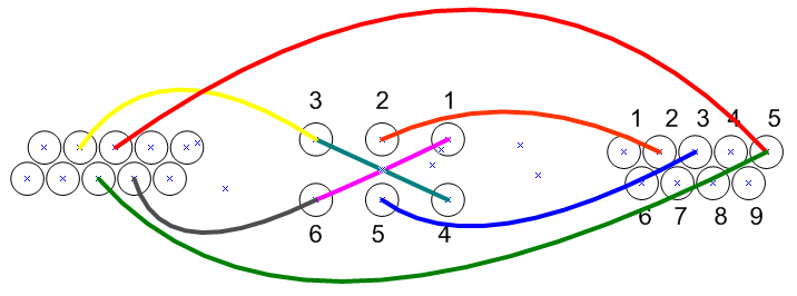
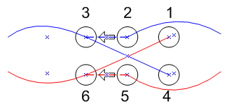
With a scrap of leftover wire (I had brown and white laying on the table at this point, but am using purple and aqua in the diagram as they show up better), cut a piece long enough to reach from pole 1 to pole 6 on the switch, and solder it in place.
Likewise, cut a piece to connect between pole 3 and pole 4 on the switch and solder it in place
Connect the orange wire to pole 2 and solder it in place.
Connect the blue wire to pole 5 and solder it in place.
Connect the yellow wire to pole 3 and solder it in place. Pole 3 will now have two wires attached to it.
Connect the black wire to pole 6 and solder it in place. Pole 6 will now also have two wires attached to it.
After the solder is cooled and secure, stuff wires down into the hole and insert the switch into the slot you cut.
Post-assembly:
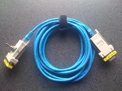
The final cable is made of the following parts, in the following order:
(gender changer)(modified rj45/db9 adapter)(straight through Ethernet cable)(unmodified rj45/db9 adapter)(gender changer)
What did I just make?
If everything is correctly assembled, the switch will operate in this manner:
With the switch thrown in direction A:
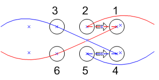
With the switch thrown in direction B:
.. which exchanges the position of the read/transmit pairs on the serial cable, switching its behavior from that of a straight through cable to a null modem cable. In a practical sense, this converts the "goddamn it I grabbed the wrong cable/disconnect/root around in your laptop bag/go out to the car to find your other cable" process into "whew, that switch is damn convenient, flip" Depending on your needs, you can also add/remove the gender changer adapters from the ends, or utilize a longer rj45 Ethernet cable. Effectively, this cuts down on the number of cables you have to carry if you administer many disparate devices.